|
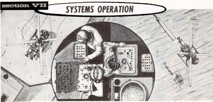
THE PRINCIPLES OF THE DASH WEAPON
SYSTEM’S OPERATION as it pertains to the QH-50D; the currently deployed variant.
The QH-50D
drone is controlled throughout its mission by the shipboard guidance system on
the ship, and by the receiving set and AFC set on the drone. (See figures 1 and
2.) Refer to figure 3 in the "Description"
Section for a listing of the components, which are included in
these groups.
Commands
originating at the deck or CIC control are fed to the selected coder where they
are translated into discrete binary coded pulses, which, in turn, are fed to the
selected transmitter. The fm output of the transmitter is modulated by the coded
pulses to produce the radio command signals to control the drone.
The
shipboard guidance system has the capability of coding and transmitting six
proportional and nine on-off commands. In the present system, the command
channels are:
1. Proportional:
-
Fore-aft airspeed (pitch).
-
Lateral airspeed (roll).
-
Heading or yaw (tip brakes).
-
Altitude (collective pitch). 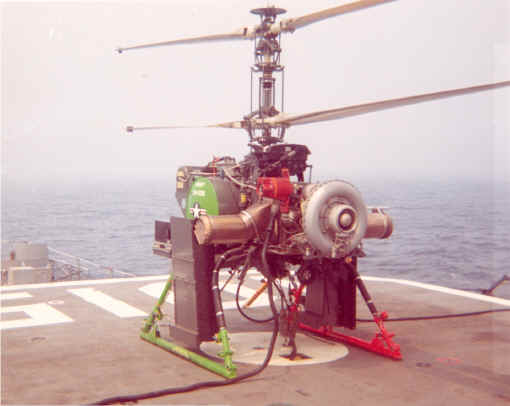
-
Spare 1.
-
Spare 2.
2. On-Off:
-
Cruise-maneuver.
-
Memory-station.
-
Engine off.
-
Cable release.
-
Weapon arm.
-
Weapon release 1.
-
Weapon release 2.
-
Spare 1.
-
Spare 2.
The proportional
channels are used to transmit commands containing magnitude and direction
information and the on-off channels are used to transmit switching information.
The
airborne receiving set completes the radio data link. The modulated FM command
signals are picked up by the airborne receiver, demodulated, and fed to the
decoder as pulses similar to those fed to the transmitter by the coder. The
decoder separates the decoded pulses into the appropriate channels and converts
them to analog values in the form of AC voltages. The drone control command
voltages from the digital-to-analog stage of the decoder are applied, at the
appropriate points, to the airborne AFC set.
The
AFC set provides the four servo loops required to convert the outputs of the
decoder to movement of the drone control surfaces, and also includes sensors,
which maintain drone stability in its commanded flight regime. Rate information
for servo system damping is derived electrically. The AFC set also contains
relays, which execute the on-off commands.

This
section, in discussing stabilization and control of the drone in the azimuth
axis, utilizes the terms "yaw" and "heading." While the two
words are not synonymous, each one is valid when used in the proper sense. The
word "yaw" is commonly used in discussions of (aircraft) stabilization
systems, where it is taken to denote “.... angular motion about the vertical
axis of an aircraft." In the present instance, in which a remote control
command is superimposed on the stabilization system, the yaw axis reference is
biased to produce a "heading" command. Heading is defined as "the
(compass) direction in which the airplane (aircraft) is pointed...." Thus,
the drone is automatically stabilized in "yaw" and its
"heading" is remotely commanded.

The four
axes in the drone stabilization and control system are listed below:
NOTE:
For purposes of clarity and
conciseness, this section describes the four stabilization and control axes as
an absolute system without regard for aerodynamic perturbations and electrical
tolerances. It is intended only that principles of system operation be discussed
in this section. Exact values relating drone response to given commands are not
included as they are not appropriate to the basic understanding of operation.
1.
Fore-Aft Airspeed (Pitch). An airspeed command is interpreted by the
drone as a demand for a longitudinal tilt of the swash plates to produce a
longitudinal thrust vector proportional to the airspeed commanded. The steady
state angle of swash plate tilt for a given airspeed command is related
principally to true vertical (with respect to earth). Swash plate tilt with
respect to true vertical is related mechanically to the pitch attitude of the
rotor mast. This mechanical relationship is maintained by summing the
measurement of pitch attitude (through the pitch pick-off in the vertical gyro)
with continuous servo follow-up position information (through the pitch
follow-up synchro in the servo actuator). In the pitch axis, the relationship of
gyro displacement to swash plate tilt (with respect to the mast) is
approximately 1.5 to 1.
2.
Lateral Airspeed (Roll). A lateral airspeed command (available in the
maneuver mode only) is interpreted by the drone as a demand for lateral tilt of
the swash plates to produce a lateral thrust vector proportional to the command.
In contrast to the pitch axis, the steady state angle of lateral swash plate
tilt for a given command is related purely to true vertical. The measurement of
roll attitude (through the roll pick-off in the vertical gyro) is summed with
servo follow-up position information (through the roll follow-up synchro in the
servo actuator) at a ratio, under steady state conditions, of 1 to 1. Thus, for
each degree of roll attitude of the rotor mast, the swash plate is tilted an
equal number of degrees with respect to the mast. During command transients or
drone deviations from the commanded flight regime, this I to I ratio is
temporarily altered, through a washout network, to enhance drone stability on
the short-term basis.
In the cruise mode, a
heading change command causes a fixed bank angle signal to be cross fed to the
lateral axis to produce a coordinated turn.
3.
Heading or Yaw (Tip Brakes). A heading command alters the heading
reference within the directional gyro system, causing extension of the
appropriate upper or lower rotor tip brakes. As the heading error signal
approaches zero, the tip brakes are retracted and the directional gyro
stabilizes the drone on its new heading. In the cruise mode, the heading change
command introduces a cross feed signal to the roll axis to produce a coordinated
turn.
4. Altitude (Collective Pitch).
The commanded drone altitude is maintained by the barometric altitude control
through the collective pitch system. An altitude command change introduces an
error signal in the collective pitch servo loop. When the drone has reached the
commanded altitude, the pick-off connected to the barometric pressure-sensing
capsule produces a voltage, which bucks out the command, bringing the error to
zero. The collective pitch system thus is readjusted until the ratio of lift
versus weight is equalized.
Electrical power for the airborne
system is provided by an AC generator, which is driven, through gearing, by the
rotor drive system. The generator provides the following nominal voltages:
115 volts,
400 cps, phase A, B, C.
22 volts, 400 cps, phase 1, 2, 3.
26 volts, 400 cps, phase A, phase
A-90 degrees.
A
three-phase rectifier circuit in the relay assembly, operating from the 22 volt,
400 cps supply, provides unfiltered 28 vdc to operate relays, solenoids, and
other equipment. The 22-volt generator winding also supplies power to two
three-phase rectifier circuits in the electronic control amplifier. One of these
circuits provides a regulated 28-vdc supply for internal use within the unit
itself. The second rectifier circuit is used in conjunction with the 28-volt
supply in a voltage doubler circuit to produce a 39-vdc supply for transistor
biases.
The weapon system has the capability of simultaneous
deployment of more than one drone from each ship. This is accomplished by
presetting three variable bits of the digital data link message structure. It is
not necessary to change carrier frequency on the controlling ship. An
eight-position address selector, which is set externally, is provided on the
decoder. Corresponding selectors are provided on the deck and CIC controls.
Prior to launching, a different address is selected on the decoder of each drone
aboard the destroyer. The first drone may be launched and placed in the memory
mode while the next one is launched. Only one drone at a time may be under
station mode control.
Although the address feature permits more than one drone to be operated
simultaneously from a single ship or station, it is still possible that a second
station, simultaneously radiating on the same frequency even though on a
different address, can cause radio frequency interference and cause the drone to
assume carrier loss or cause the passage of spurious commands. The likelihood of
such an occurrence is dependent upon the relative signal strength of the two
stations.
When
the drone is placed in the memory mode, it continues to fly at its last
commanded altitude, airspeed, and heading until the controller switches back to
the station mode and introduces a new command.
If carrier is lost while the drone
is on memory, it remains on memory. If carrier is lost while the drone is under
station control, the cyclic pitch controls move to neutral, and the drone
assumes a "No wind" hover at its last commanded altitude and heading.
In the cruise mode, a time delay circuit (carrier loss smoothing module) in the
pitch axis prevents severe drone pitch up when carrier is lost or severe pitch
down when carrier is restored.
Within the flight envelope set forth in Section V, a
collective pitch limiting system functions to prevent excessive drop in rotor
rpm in the event of excessive aerodynamic loading. This limiting system, which
operates as a function of rotor rpm error, includes a frequency sensor, which
provides a varying de voltage output proportional to frequency variations of the
input obtained from the airborne generator. If the rotor rpm drops below
approximately 98 percent of rated rpm, due to a rotor overload resulting from
excessive command, a command-bucking signal is applied to reduce the magnitude
of the command. This bucking signal is applied to the altitude axis to reduce
rotor loading through the collective pitch system.
The
engine-off command, through the data link, removes the gyro output signals from
their respective servo axes, so that the rotor system will not be affected by
destroyer pitch, roll, and yaw while the rotors are slowing down.
MESSAGE CODING MECHANIZATION
Proportional channel commands are generated by the positioning of the manual
controls, which, in turn, are mechanically coupled to digital shaft encoders.
The digital shaft encoders translate shaft positions into various coded switch
closures. The coded switch closure information is then fed through a relay
assembly to the audio frequency coder. The coder converts these switch closures
into a series of pulses. A pulse represents a closed switch, and the lack of a
pulse represents an open switch. In the binary digital system, a pulse is
indicative of “1”, and the lack of a pulse signifies "0". Each
switch is assigned a position in the binary numbering system and is referred to
as a binary digit or bit.
Thus,
when a proportional channel command is applied, the associated digital shaft
encoders generate a series of pulses, which are then translated into a frequency
shift keyed (FSK) signal. The FSK signal can have one of two frequencies at a
given time. One frequency represents the binary "1" and the other
frequency represents the binary "0". The FSK signal becomes a constant
amplitude signal, which switches from one frequency to another responding to the
coded pulses. This frequency shift is referred to as a pulse code modulation of
a frequency modulated subcarrier (pcm/fm). The FSK signal from the coder
is introduced into the transmitter.
The radio transmitter is a frequency-modulated (fm) transmitter containing a
network, which transforms the FSK signal into a signal to frequency, modulate
the RF carrier. When the FSK signal is applied to the radio transmitter, it is
coupled to the internal power supply. The signal is then fed to the amplifier
modulator stage to modulate the RF carrier. The output of the amplifier
modulator is then raised to the transmitting frequency and the proper power
requirements by the frequency-multiplier-amplifier stage. The final output
signal is transmitted through the antenna to the drone.
STABILIZATION AND CONTROL AXIS MECHANIZATION
GENERAL
PRINCIPLES
Movement of the aerodynamic control surfaces (rotor blades and tip
brakes) of the drone is achieved by the introduction of an error signal into the
input to the appropriate servo amplifier module in the electronic control
amplifier. The output of the servo amplifier module is applied to one or the
other of the two oppositely rotating
electromagnetic clutches in the related axis of the servo actuator, and the
output arm is driven in a direction characteristic of the polarity of the error
signal. A velocity generator, internal to the servo actuator, and geared to the
output arm, provides rate information to the minor loop for purposes of damping
and loop stability.
A synchro, also geared to the output arm, provides servo actuator output
position (follow-up) information required for minor loop stability. This
information is utilized in several ways in the various axes. Depending on the
operating regime (on deck or in normal flight), all or part of the follow-up
signal may be applied to a washout network. The washout network permits the
follow-up signal to pass through on a transient basis; on a long term basis
(depending on the washout time constant) the follow-up signal is decayed
essentially to zero. The manner in which the follow-up washout it utilized is
described as follows for each of the four axes. When the drone is operating on
the deck, it is necessary to eliminate the effect of the washout circuitry in
order to avoid undesirable control positions. The landing gear skid switches are
utilized to short out, or disconnect, the washout circuits.
FORE-AFT
AIRSPEED
The
fore and aft airspeed command output of the decoder is an ac voltage with a
phase characteristic of the direction commanded and a magnitude
proportional to the speed commanded. This signal is applied, through summing
networks, to the servo amplifier to cause the servo actuator to move the swash
plates in the longitudinal cyclic axis. (See figure 3.) The summing networks in
the command path also accept information from the vertical gyro pitch pick-off
as well as servo actuator follow-up position information. When the magnitude of
the combined gyro and follow-up inputs equals the magnitude of the command input
the servo loop is nulled with the controls positioned to cause the drone to fly
at the commanded airspeed.
The flight characteristics of the drone are such that the pitch attitude versus
airspeed curve is relatively flat in the region of 0 to 50 knots. When pitch
attitude alone is measured (through the gyro pitch pick-off) and used for
position information, a low gain system results and precise airspeed control in
the low speed range is difficult to achieve.
The curve of swash plate tilt
(with respect to the mast) versus airspeed is steep in the 0 to 50 knot range
and levels off in the upper range. When the two functions (pitch attitude and
swash plate tilt) are measured and summed algebraically, the curve representing
airspeed command versus the sum of gyro and follow-up becomes very nearly
linear, and more precise control in the low speed range is achieved. This system
is mechanized by applying the follow-up synchro output to the input leg on a
continuous basis (not washed out). The resultant signal [command - (gyro +
follow-up)] is amplified in the appropriate module in the electronic control
amplifier. The output of the servo amplifier module is applied to the servo
actuator to position the swash plates at the angle required to produce the
commanded airspeed.
LATERAL
AIRSPEED
The manner in which
a lateral airspeed command is applied to the drone control system is similar to
that of the longitudinal axis. (See figure 4.) The command output of the decoder
is applied, through summing networks, to the servo amplifier in the lateral
cyclic axis. The output of the servo amplifier is applied to the electromagnetic
clutches in the servo actuator to cause the swash plates to tilt in the
appropriate direction. The follow-up signal from the synchro in the servo
actuator is summed with the roll attitude information from the roll pick-off in
the vertical gyro and applied to the input leg of the servo amplifier to buck
the command signal.
In flight, the
follow-up signal passes through a washout network and a fixed gain follow-up
network. The washout network has a time constant of 4 to 6.2 seconds, after
which time any signal initially passing through it is decayed essentially to
zero. The washout network provides short term loop stability during transients.
The fixed gain follow-up network allows 50 percent of the total follow-up signal
to remain in the loop on a steady state basis. This “50 percent washout"
system permits the lateral cyclic axis gains to be determined such that, for
steady state conditions in a hover, each one degree of roll attitude (gyro
signal) is equal to one degree of swash plate tilt relative to the rotor mast
(follow-up signal).
When
one of two side-by-side weapons is dropped, the center of gravity of the drone
shifts laterally toward the remaining weapon. This CG shift causes the drone
rotor mast to assume an approximate 3-degree roll attitude. This angle is
measured by the roll pick-off in the vertical gyro and the resultant signal is
applied to the input to the servo amplifier and servo actuator output results.
During the time the drone is rolling into its new attitude the follow-up signal
is fed back to the input to the servo amplifier through the wash out network to
maintain drone stability during the roll transient.
When the drone attains its new steady state roll attitude,
only the 50 percent fixed gain follow-up signal remains in the loop. Under this
condition the follow-up signal equals the gyro signal and the swash plates
remain tilted, with respect to the mast, by an amount equivalent to the roll
attitude of the mast. Thus the swash plates remain normal to true vertical, the
thrust vector passes through the new CG, and no lateral flight of the drone
results.
When the second weapon is dropped, the
CG shifts back to center and the rotor mast returns to a zero roll attitude.
Following the roll attitude and follow-up washout transients, the gyro and
follow-up signals are reduced to zero and swash plate tilt is maintained at zero
with respect to both the rotor mast and true vertical.
When
the drone is on the deck, the washout network is disconnected by the skid
switches. Under this condition, true and continuous follow-up information is fed
back to the input to the servo amplifier to buck the command signals applied for
system checkout purposes. Thus, actual swash plate tilt for given command inputs
can be verified.
In flight, in the cruise mode, a
signal originating in the heading axis is applied to the input to the roll axis
to produce coordinated turns on the application of a heading change command. The
magnitude of the turn coordination signal is such that a fixed roll angle
displacement of approximately 20 degrees results. Turn rate is automatically
adjusted as a computed function of airspeed to satisfy the aerodynamic
requirements.
HEADING
The
heading axis servo system functions in a manner similar to the pitch and roll
axes. Differences exist in the servo follow-up circuitry and in the manner of
the application of the command to the servo system. (See figure 5.)
Heading commands are
applied to the servo system through a heading data converter, which includes a
motor-driven synchro transmitter, velocity generator, and two follow-up
potentiometers whose wipers are positioned 180 degrees apart. The pulse coding
of the heading command is discrete for each of two sectors: 0 to 178.6 degrees,
and 180 to 358.6 degrees (Each of the 1.4 degree gaps is the equivalent of one
bit of the coded message. This is the smallest increment that can be resolved in
the digital heading command system.) Each of the two potentiometers bears a
fixed relationship to a given heading sector. As the heading pointer is turned
past 0 or 180 degrees on the heading card, the pulse code changes, and a relay
in the decoder switches the system electrical connections from one follow-up
potentiometer to the other.
The
heading command output from the decoder is an AC voltage which increases in
amplitude through the same range as the pointer is turned from 0 to 178.6
degrees and from 180 to 358.6 degrees. The command voltage is amplified and
applied to the motor in the heading data converter. The motor drives until the
related potentiometer nulls the closed loop. The motor positions the rotor of
the synchro transmitter whose stator is connected to the stator of a
differential synchro in the directional gyro control unit. The rotor of the
differential synchro is connected to the stator of a synchro control transformer
whose rotor is positioned by the gyro gimbal. The error signal from the gyro
pick-off is shaped, amplified, and applied to the tip brake axis clutches in the
servo actuator.
When the drone is airborne and a heading change command is
applied to the servo amplifier, the follow-up signal is fed back to the servo
amplifier through the washout network. As the drone begins to turn to the new
heading the follow-up signal is washed out and the heading command error remains
as the primary input to the servo amplifier. As the drone approaches the new
commanded heading, the error signal is reduced to zero, the servo actuator
retracts the tip brakes, and the drone is stabilized on its new commanded
heading.
Aerodynamic
forces in the rotor system when the drone is in forward flight tend to create a
torque imbalance in the rotor drive system. This causes the drone fuselage to
tend to deviate from its commanded heading. The resultant error signals from the
directional gyro are applied to the servo amplifier to provide corrective servo
actuator output. As the drone returns to its commanded heading, the gyro error
signal is reduced to zero and the servo follow- up signal is washed out with the
tip brakes on one of the rotors extended by the amount required to remove the
torque imbalance.
When the drone is on the deck with rotors turning and a
heading change command is applied, the servo actuator output arm is displaced in
the appropriate direction. Since the washout network is shorted out through the
skid switches, follow-up position information is fed back directly to the servo
amplifier input to reduce the heading error. Servo actuator output arm
displacement is proportional to heading error from 0 to approximately 34 degrees
of heading error. At that point the servo actuator output arm is displaced to
its limit and follow-up position information is at its maximum value. A heading
change command of more than 34 degrees causes an error signal proportional to
the difference between command and maximum follow-up to remain applied to the
input to the servo amplifier.
Airspeed
data is cross fed to the heading axis to regulate turn rate as a function of
airspeed for coordinated turns. The airspeed data consists of pitch attitude
plus follow-up position information modified so that the signal applied to the
heading axis represents swash plate tilt with respect to true vertical (true
airspeed). The velocity generator in the heading data converter also supplies a
signal to the roll axis to create a bank angle for turn coordination in the
cruise mode.
Prior to launching the drone, the directional gyro is slaved
to (aligned with) the ship gyro system so that the drone heading in flight
always is related to true north.
ALTITUDE
Altitude information is obtained from the barometric altitude
control, which includes an inductive pick-off mechanically connected to a static
pressure capsule. The internal mechanism is automatically adjusted, prior to
launch, to null the electrical output at the prevailing ambient barometric
pressure.
The
altitude command from the decoder is summed with the output of the barometric
altitude control, amplified, and applied to the collective pitch axis clutches
in the servo actuator. (See figure 6.) A liner loop damping, follow-up, and
washout are mechanized in a manner identical to the heading axis.
When
an altitude or change of altitude command is applied, an error signal is
introduced into the input to the servo amplifier and servo actuator output
results. Collective pitch is increased or decreased to cause the drone to ascend
or descend as commanded. As the drone changes altitude, the barometric altitude
control senses the change in barometric pressure and causes a signal to be
applied to the summing network in opposition to the command signal. When the
commanded altitude is attained the error is reduced to zero and the servo
actuator maintains the collective pitch setting at that required to maintain
lift. Since the barometric altitude control senses only barometric pressure (as
a function of altitude) the collective pitch system is automatically adjusted as
required regardless of ambient temperature and drone gross weight.
When
the drone is airborne, the follow-up signal is washed out to remove the
collective pitch position information from the servo loop. Thus the input to the
servo amplifier is the sum of command and barometric altitude control output.
When the drone is on the deck, the washout network is shorted out by the skid
switches so that position information remains in the loop. This permits a check-
out of control position versus command input on the deck, without drift of the
control linkage, which would otherwise result.
End of Systems Operation Section
           

|