|
MANEUVERABILITY
The drone is a highly
maneuverable helicopter of the coaxial rotor type. Under steady state fuselage
heading conditions, the torque delivered to one rotor is exactly equal and
opposite to the torque delivered to the other rotor. Thus, there is no need for
any aerodynamic counter-torque device to keep the fuselage stable. Fuselage
heading change is achieved by temporarily increasing the aerodynamic drag on the
appropriate upper or lower rotor by means of the tip- brakes. Extending the tip
brakes on the upper rotor introduces an unbalance torque, which feeds back
through the transmission to turn the fuselage to the right; extending the tip
brakes on the lower rotor causes the fuselage to turn to the left. Cyclic and
collective pitch controls are conventional; i.e., directional (translational)
flight is achieved by tilting the swash plates, vertical flight is controlled by
moving the swash plates axially on the rotor mast.

The
word "translational", as used in this sections and those part of this
series and in general helicopter terminology, is taken to denote movement of the
helicopter, with respect to the surrounding air mass, in a generally horizontal
direction, in any azimuth direction, irrespective of fuselage heading.
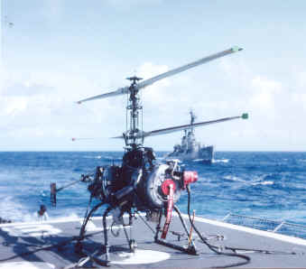
There are no pilot's
controls on the drone. Control surface motion is achieved remotely by the
manipulation of the deck and CIC control knobs and maneuver stick.
The maneuver stick has command
authority, which can cause the normal cruise Vmax of the drone to be exceeded.
This authority must be used with extreme care, and for command transients only.
Refer to the operating limitations in the section “Operating Limitations”.
CENTER OF GRAVITY SHIFT
 The drone is capable of carrying one weapon centrally located or two equal
weight weapons side-by- side. When a central weapon is dropped, the CG moves
upward. When one of two side-by-side weapons is dropped, the CG shifts upward
and sideward. When both side-by- side weapons are dropped, the CG shifts upward.
The drone is capable of carrying one weapon centrally located or two equal
weight weapons side-by- side. When a central weapon is dropped, the CG moves
upward. When one of two side-by-side weapons is dropped, the CG shifts upward
and sideward. When both side-by- side weapons are dropped, the CG shifts upward.
When the CG shifts upward there is a
change in the pitch attitude and true airspeed of the drone, for any given
airspeed command. Refer to the airspeed calibration data in the section
“Performance Data”.
When one of two
side-by-side weapons is released the CG shifts laterally. With this asymmetrical
CG the mast tilts approximately 3 degrees laterally about the center of rotor
thrust. In order to maintain drone stability under steady state conditions, the
thrust vector must pass through the CG. The servo system gains in the roll axis
provide one degree of swash plate tilt, with respect to the mast, per degree of
roll attitude, as measured by the roll pick-off in the roll and pitch gyro.
Thus, as the drone cg shifts laterally, an approximate 3-degree roll attitude is
introduced and the gyro senses the error. The roll axis servo system tilts the
swash plate to compensate for the tilt of the mast and drone stability at this
attitude is maintained.
Though the swash plate is tilted in roll
with respect to the mast, sufficient authority remains for normal maneuvers.
AUTOROTATION
It is not possible to
land the drone in autorotative flight.
HOVERING
With the maneuver
stick at center or zero airspeed commanded, the drone will assume a
"no-wind" hover, i. e., it will remain fixed over a spot on the earth
in calm air. By applying the appropriate directional command, the drone may be
made to hover over the spot when the wind is blowing, or over the deck of the
ship under way.
The power required for a "no-wind" hover is greater than the
power required in directional flight at low and moderate speeds. Therefore, fuel
is consumed at a greater rate.
CRUISING
In
the cruise mode, the drone is controlled through the heading (tip brake),
altitude (collective pitch), and airspeed (longitudinal cyclic pitch) axes. In
forward flight, turns are automatically programmed. The bank angle in turns is
fixed at approximately 20 degrees, with respect to steady state flight attitude,
and turn rate is automatically adjusted to satisfy the coordination requirement
as a computed function of airspeed.
Within the altitude
limits set forth the section “Operating Limitations”, a collective pitch
limiting system serves to prevent excessive drop in rotor rpm in the event of
excessive aerodynamic loading. When an abrupt altitude command (or altitude
error signal) causes aerodynamic overloading of the rotors, rotor rpm tends to
decrease. If, as a result, rotor speed drops below approximately 600 rpm, a
limiting bias is applied to the input to the altitude axis servo amplifier to
reduce the magnitude of the error signal, and the collective pitch setting of
the rotor blades is reduced. This rpm error cross feed limiting functions
throughout all flight regimes in both maneuver and cruise modes.
AIRSPEED VS ALTITUDE
CHARACTERISTICS
When the drone is a "no-wind" hover,
it seeks to maintain its commanded altitude, within the range of tolerance
inherent in the airborne altitude control system. As the drone moves into
forward flight, a decrease in altitude will occur at an average rate of one foot
of altitude per each knot of true airspeed. For example: as the drone
accelerates from a "no- wind" hovering altitude of 300 feet to a
forward air- speed of 50 knots, it will lose altitude at the rate of one foot
per knot until it re aches 250 feet and 50 knots true airspeed, at which point
it will level off and continue to fly at that altitude. Thus the drone always
flies at an actual altitude that is lower than its hovering altitude by an
amount (in feet) proportional to its true airspeed (in knots).
 This deviation from the hovering altitude is the result of aerodynamic
perturbations in the region of the static pressure pick-up in translational
flight. As the drone moves through the surrounding air m ass, a region of
slightly reduced pressure is created above the circular air deflector at the top
of the mast. This reduction of pressure is proportional to airspeed. The static
pressure pick-up, above the air deflector, senses the reduced pressure and the
barometric altitude control interprets it as a plus (or positive) altitude
error. The collective pitch system seeks to correct the apparent error and the
drone altitude de- creases until the pressure in the region above the deflector
increases to that normally existent in undisturbed air at the original hovering
altitude. At that point the altitude retention system nulls and the drone
continues to fly at that altitude as long as its airspeed remains constant. Any
change in drone airspeed will result in a corresponding change in actual
altitude. Just as the drone altitude decreases during acceleration, its altitude
increases at the same rate during deceleration.
This deviation from the hovering altitude is the result of aerodynamic
perturbations in the region of the static pressure pick-up in translational
flight. As the drone moves through the surrounding air m ass, a region of
slightly reduced pressure is created above the circular air deflector at the top
of the mast. This reduction of pressure is proportional to airspeed. The static
pressure pick-up, above the air deflector, senses the reduced pressure and the
barometric altitude control interprets it as a plus (or positive) altitude
error. The collective pitch system seeks to correct the apparent error and the
drone altitude de- creases until the pressure in the region above the deflector
increases to that normally existent in undisturbed air at the original hovering
altitude. At that point the altitude retention system nulls and the drone
continues to fly at that altitude as long as its airspeed remains constant. Any
change in drone airspeed will result in a corresponding change in actual
altitude. Just as the drone altitude decreases during acceleration, its altitude
increases at the same rate during deceleration.
When the drone enters into a turn in the cruise
mode, it may experience an additional loss of altitude, and the extent of such
loss will be a function of the duration of the turn. Initially, the loss of
altitude will result from the sudden lateral displacement of the thrust vector
by approximately 20 degrees (the nominal fixed bank angle of the drone in a turn
in the cruise mode), thereby altering the vertical thrust-to- weight ratio. In
the event of misadjustment in the electrical turn coordination system, there may
be superimposed on the initial loss of altitude an additional decrease in
altitude if the drone tends to slip, or an increase in altitude if the drone
tends to skid. As the barometric altitude control senses the deviation it will
readjust the collective pitch system to compensate. Normal operations in the
cruise mode should be limited to a minimum commanded altitude of 300 feet.
ROTOR BLADE STALL
The likelihood of entering into rotor blade stall in the QH- 50D drone is
lessened by the reduction in range of certain factors, which normally contribute
to blade stall, as follows:
1. The tactical
altitude envelope is limited to 0 to 1000 feet by the command range of the
system.
2. Rotor speed is fixed at a nominal 610
rpm by the regulating systems on the drone.
3. Bank angle in coordinated turns is
fixed at approximately 20 degrees and turn rate is automatically adjusted as a
computed function of airspeed to satisfy the turn coordination requirements.
4. The weight
configurations of the drone are fixed within a well defined envelope.
With the reduction of
the variability of the above factors, the only other contributory factors are
airspeed, temperature, and high g-loading.
Ambient
temperature has an effect on blade stall as it has on normal helicopter flight
characteristics.
The low density
usually accompanying high temperature reduces the airspeed at which the onset of
blade stall might occur.
In a helicopter, incipient blade stall usually manifests itself
initially as a slight vibration of a non-critical nature. If this were to
occur in the QH-50D drone, it would not be detectable since the drone is not
equipped with tactical telemetry. In the QH-50D drone, blade stall can occur
only under the following unusual circumstances, all of which relate to excessive
airspeed:
1. Drone operations at
Vmax in strong gusty weather. Under these circumstances, blade stall may be
encountered in gusts on a short term or transient basis. Any resultant vibration
should cause no damage to the drone.
2. Failure to observe
safe operating procedures. Operations outside the operating envelope set forth
in Section V should be avoided.
3. Misadjustment or malfunction in the
automatic turn coordination system. During a mis-coordinated slipping turn,
which is evidenced by a loss of altitude, it is possible for the drone to
experience blade stall. In this case, the loss of altitude is more critical than
the possible resultant blade stall. Corrective commands should be applied
immediately in an attempt to arrest the slip and thus maintain altitude. These
corrective commands (reduction of airspeed) automatically will reduce the
magnitude of the blade stall effect and, as the drone recovers, remove it
completely.
POWER
SETTLING
Power settling is a phenomenon inherent in all helicopters and is characterized
by an uncontrolled and excessively high rate of descent. The possibility of
entering into a true power settling condition is created when initiating a
descent from a "no wind" hover or while at low airspeed, particularly
at higher gross weights. It is normal in a hover for the down- wash velocity to
vary along the span of the rotor, in- creasing from hub to tip, i. e. the
downwash velocity is lower near the center of the rotor disk area than it is
near the outer portion. In a rapid descent, the rotor literally "settles
into its own downwash. " In the area of low downwash velocity (the center
of the disk), rotor thrust will be reduced, and, as the rate of descent
increases, the area of reduced thrust be- comes larger. If the rotor net thrust
is reduced sufficiently, the helicopter is effectively free-falling. In the
QH-50D drone, if a large reduction in altitude is commanded rapidly, the drone
will descend and its rate of descent can be of such magnitude that the rotors
can enter into their own downwash pattern.
The most effective
recovery technique is to apply or increase translation airspeed command. As the
rate of descent decreases, further changes in altitude can then be achieved by
using the altitude rate switch or by manually applying gradual altitude
commands.
Under any
circumstances, the conditions contributing to incipient power settling should be
avoided at all times.
AIRFRAME VIBRATION
Airframe vibration is a phenomenon inherent in
all helicopters. The characteristic frequency of these vibrations is generally a
function of the number of rotor blades and the rotor speed. In the QH- 50D the
common frequencies are approximately 5, 10, and 20 cycles per second. In a
normally rigged and balanced vehicle, this vibration frequency will appear in
one or more axes, and may be observed as small amplitude control oscillations.
However any one of several
factors may cause the control oscillation amplitude to increase to the extent
that the attitude of the drone is visibly affected. This condition may be caused
by mistracking, unbalanced rotors, bent rotor shafts, or marginal servo-
actuator, etc. If this abnormal condition is noted, the drone should be landed
immediately and the cause found and eliminated prior to further flight.
EFFECTS PECULIAR TO
SHIPBOARD OPERATION
TURBULENCE
In all maneuvers in the
vicinity of the ship, wind direction and velocity must be taken into account.
When the relative wind is directly abeam, astern, or ahead, the ship
superstructure causes the wind to become turbulent over the flight deck. This
turbulence must be taken into account in launching and landing the drone. In
contrast, wind striking the ship superstructure at an angle is deflected
laterally, instead of vertically, and less turbulence over the deck results.
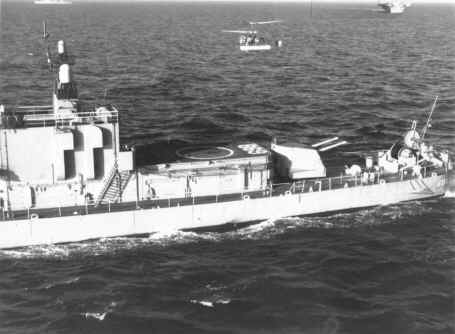
 SHIP
MOTION SHIP
MOTION
When the ship is
under way, compensation must be made, in launching, and landing the drone, for
forward speed of the ship. If the drone is to hover over the deck, an equivalent
airspeed must be maintained to compensate for relative wind velocity. Following
the launch, it is imperative that this airspeed be maintained, and then
gradually increased so that the drone moves out in the direction into the wind.
If the airspeed is decreased and the drone is allowed to drift downwind, it is
probable that settling will occur. At higher temperatures and normal gross
weight configuration, this practice is dangerous. After switching to the
cruise mode, downwind turns can be made with safety, provided that a minimum
airspeed of 20 to 25 knots is maintained prior to entering into the turn.
Launching and landing
the drone when the deck is pitching, rolling, and yawing requires
synchronization of commands with the movement of the deck. In general, it is
preferable in a launch, that the drone breaks contact with the deck when the
deck is moving in the upward direction and rolling in the direction into the
relative wind. In landing, it is preferable that the drone makes contact with
the deck when the deck is moving downward.
End of Flight Characteristics
Section


|