 Nite
Panther was conceived as a derivative of the Advanced Research Projects Agency's
(ARPA) Nite Gazelle Program using the U. S. Navy's QH-50 DASH - (Drone Anti Submarine
Helicopter) System which was originally designed to provide destroyers with
stand-off capabilities for the delivery of MK-44 torpedoes against submerged
submarines. Nite
Panther was conceived as a derivative of the Advanced Research Projects Agency's
(ARPA) Nite Gazelle Program using the U. S. Navy's QH-50 DASH - (Drone Anti Submarine
Helicopter) System which was originally designed to provide destroyers with
stand-off capabilities for the delivery of MK-44 torpedoes against submerged
submarines.
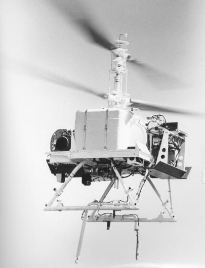
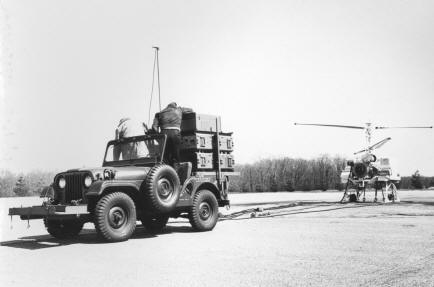
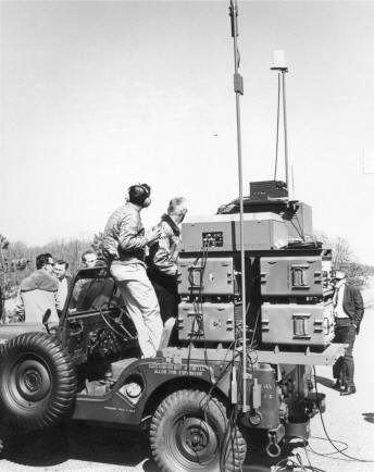
Nite Panther was a reconnaissance/observation system which provided a real time
visual display day or night through the medium of a remotely controlled and
commanded television equipped Model QH-50 helicopter and a Model M38A1, 1/4 Ton,
4x4 Truck Control Station, seen below right.
The system had the capability to perform spot search, specific area search,
small area reconnaissance, target detection and identification, indirect fire
adjustment and assist in establishing and maintaining perimeter defense security
for both base camp areas and deployed unit locations.
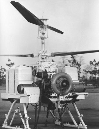
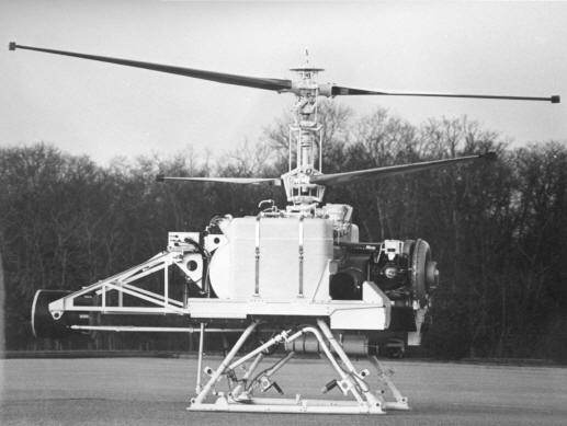
The Model QH-50D is a
stable sensor platform still in use today which has a degree of stability such as to minimize
introduction of degradation or loss of resolution into the image returns being
provided by the television sensor due to platform movement.
The Model M38A1 used was a standard jeep which had been adapted to carry a modified
Target Control System AN/SRW-4B as the command link between the ground and the
airborne vehicle in addition to start up equipment for the QH-50 and for
receiving, monitoring, recording and subsequent playback of television
information generated by the airborne vehicle. In addition, the jeep had been
outfitted with a Special Support Telemetry System to monitor 38 data parameters
and two synchronizing channels which were processed by the airborne telemetry
system.
|
|
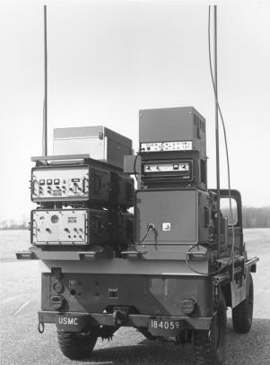
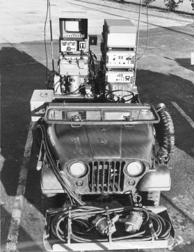
The Rear View of the "Jeep Control Station".
On the left side, from top to bottom is the Video Recorder, Telemetry
Receiver and Telemetry Antenna Controller.
On the right side, from top to bottom is the TV Monitor, TV Receiver and
Telemetry Data Display Unit
|
|

|
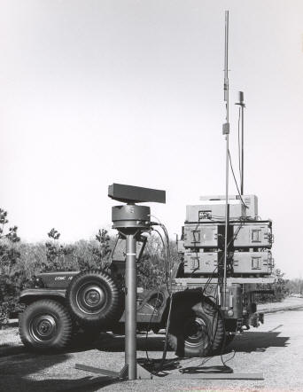
The Side View of the "Jeep Control Station".
On the left side of the photo, from top to bottom is the
Telemetry Receiving Antenna Assembly placed on the Telemetry Antenna Mast.
The Antenna's seen at far right consist of the TV Receiving
Antenna, Command Antenna and the TV Transistorized Amplifier.
|
|
There were TWO separate JEEP installations; the one above which was ONLY a
Command, Control with remote TV monitoring station and another installation
which had "Start" AND Command and Control
capability - That Installation was called the
COMMAND-START JEEP and is seen as follows.
|
|
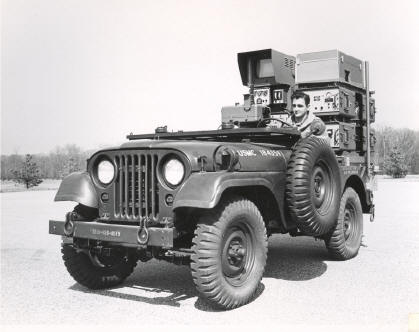
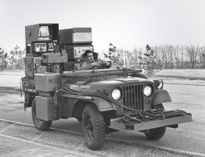
The Front and Side View of the "Jeep-Command-Start Station".
On the left side of the photo, over the front fender
are the Antenna Extensions. Next to the passenger seat, is the Auxiliary
relay assembly, Command Transmitter and Control Monitor.
|
In the back of the Jeep, on the
left side from top to bottom is the TV Monitor, Receiver and Remote Azimuth
indicator.
On the right side was located the Video
Tape recorder, DME and Multiplexer.
On the very front of the Jeep are the
Automatic Flight Control System (AFCS) and Engine Umbilical Cables.
|
|
Based on discussions with representatives from the Advanced Research
Projects Agency of the Department of Defense, the Gyrodyne Company of America,
Inc. on 7 March 1968 commenced implementation of the Nite Panther Program
concept in response to an urgent operational requirement for the U. S. Marine
Corps.
The subsequent sequence of events followed:
20 March 1968
|
Gyrodyne submitted a telegraphic technical and cost proposal for the
Nite Panther Program
|
1 April 1968
|
A Naval Air Systems Command Letter Contract was received by Gyrodyne
authorizing delivery of two mobile ground control stations based on JEEP
platforms and three Model QH-50D's modified for ARPA's Nite Panther concept.
|
3 April 1968
|
One QH-50 Nite Panther, Serial No. DS-1700 and one jeep control station
were shipped to San Clemente Island for use in the initial training of
designated Marine Corps personnel.
|
7 April 1968
|
Two Nite Panther vehicles, Serial No. DS-1701 and DS-1702 plus a jeep
control station with a QH-50 start capability were shipped to San Clemente
Island.
|
18 April 1968
|
The delivered items, support equipment, trained Marine Corp personnel
and Gyrodyne technicians were deployed from San Clemente Island.
|
The Advanced Research Project Agency's Nite Panther concept
was a reconnaissance/observation system which provided for transmission of real
time television information from an airborne platform to shipboard or mobile
ground control stations. Such real time television information was obtained,
day or night, from a remotely controlled TV system mounted aboard a Model QH-50
unmanned helicopter which was commanded from either the shipboard or jeep
control station.
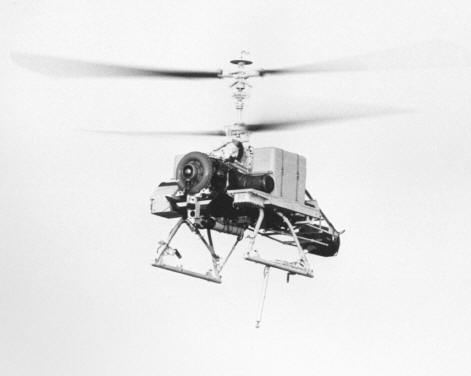
In addition to the television system as a primary sensor, the QH-50
helicopter was equipped with a telemetry system (including distance measuring
equipment (DME)), altitude measuring devices, and a laser range-finder. Two (2)
auxiliary fuel tanks were also provided aboard the airborne vehicle to provide
extended mission range capability over that normally available in the basic 52
gal. tank. Radar transponders for enhancement of surface radar return signals
were provided as well as a still picture photographic camera.
THE AIRBORNE PLATFORM
Functionally, the QH-50 Nite Panther airborne platform provided for the
following:
-
Observation of
the ground using a television camera with either a daytime or nighttime
capability, and transmission of the TV information back to the ship- board or
jeep control station.
-
Reception of
commands from the control station and operation of the TV camera (including
associated lens or the IR illuminator), the laser range-finder, and the still
photographic camera.
-
Measurement of aircraft status and transmission of information back to the
control station.
-
Measurement of aircraft altitude and rate of climb (if implemented) and
transmission of this information back to the control station.
-
Determination
of slant range from the QH-50 vehicle to the ground point or area being
observed by the TV camera and transmission of this information back to the
control station.
JEEP Control Stations
The Model M38A1 was a standard jeep which was adapted to carry
command. telemetry, and television equipment with the necessary power supplies.
Functionally, this control station provides for the following:
1. Start up and pre-flight checkout of the
QH-50 vehicle.
2. Command of the aircraft from takeoff to
touch- down. Provision was made for takeover from and handover to either a
shipboard control station or another Truck Control Station.
3. Monitoring of aircraft
status while in flight.
4. Tracking of the aircraft
and determination of its azimuth and slant range relative to the Truck Control
Station.
5. Receiving, monitoring,
recording and playback of television information transmitted from the airborne
station.
SHIPBOARD Control Station
The shipboard
control station was the basic DASH station
modified and augmented to provide the expanded command, telemetry, and
television capabilities of the Nite Panther system. In addition to those
functions provided in the Truck Control Station, the shipboard control station
provided complete support for the Nite Panther QH-50 vehicle.
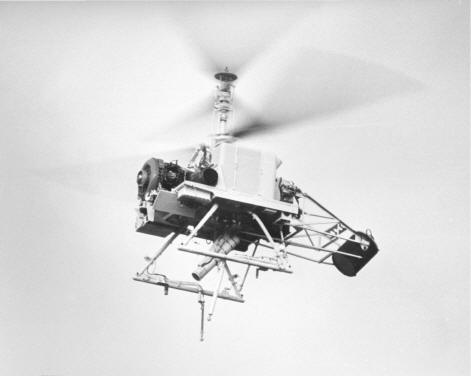
 Television System Television System
The television system was comprised of three stations, one
airborne, one shipboard and one on the jeep. At the shipboard and jeep stations,
it was possible to view a real time television picture of the area under
observation by the TV camera aboard the QH-50 helicopter (seen
at left). The television system operates on one RF center frequency
in the microwave region and the video information (15 MHz baseband) was
transmitted, at a 20-watt level, by FM techniques. Either a daylight high
resolution monochrome TV camera or a low light level monochrome television
camera could be mounted on the QH-50 helicopter. Remote control of either camera
and associated lens was exercised from either the shipboard or the jeep control
station through the command link. Equipment was provided in both control
stations for receiving, monitoring, recording, and subsequent playback of
television information generated by the airborne TV station.
A
Dynalens was provided for dynamic optical compensation of the effects of camera
vibration on the TV picture. This lens could be mounted to either the daylight
or low light level TV camera.
The
daylight TV camera utilized a 924-line raster and employs a remotely operated
zoom lens which permitted closer viewing of objects of interest on the ground or
viewing of a wide field for pilotage or observation purposes.
The
TV camera tilt angle could be commanded remotely from either the shipboard or
the jeep control station. The tilt angle could be controlled from horizontal
down to a 90 degree depression angle.
The low light level TV camera utilized a 525-line raster and
employed a fixed focal length lens. An infrared illumination light for use in
conjunction with this camera to supplement natural nighttime illumination was
eventually mounted on the QH-50 helicopter. This illumination source was then
tilted remotely from the control station such that its axis remains parallel to
that of the low light level TV camera.
Command System
The command system employed two command links,
a Target Control System, AN/SRW-4B, as the RF command link between the shipboard
control station and the airborne station; and the Radio Transmitter AN/ARW-80
link between the jeep control station and the airborne station. Portions of the
AN/SRW-4 were also employed in the jeep control station.
Command of both the QH-50 helicopter itself and the sensor systems aboard was
accomplished, in the case of each control station, through the respective
command link.
The command system was modified at the control
station and in the airborne station to accommodate the increased requirements of
the Nite Panther. In this modification the functions of: weapon arm, weapon
release 1, weapon release 2, cable release, spare 1, spare 2, spare command word
# 3, and command word # 6, of the basic DASH system were utilized or modified to
provide for the following Nite Panther commands:
-
Daylight TV
camera: tilt up-down, focus near-far, iris open-close, zoom in-out, RF and
camera on-off.
-
Nighttime TV
camera: tilt up-down, focus near-far, iris open-close, video gain low-high, RF
and camera on-off, IR light on-off and tilt up-down.
-
Still
photographic camera: on-off.
-
Laser
rangefinder: on-off.
-
Extended
altitude range: mode selection and control
-
Turn
coordination: in-out.
-
Running lights:
on-off.
 Telemetry System Telemetry System
The telemetry system consisted of three portions,
one on the QH-50 helicopter, one at the shipboard control station and one at the
jeep control station. This system provided the dual purpose of determining the
position of the QH-50 helicopter; and of providing information to each control
station pertaining to the operational status of the airborne station.
The
telemetry system employed PAM/FM/FM techniques and operated at microwave
frequencies. The DME (Distance Measuring Equipment) was an integral portion of
the telemetry system and permitted determination of the slant range of the QH-50
helicopter from each control station. The command transmitter in each control
station was utilized to transmit the range tone from either the shipboard or
jeep control station.
Laser Rangefinder
The laser rangefinder was
provided to permit accurate determination
of the slant range from the QH-50 helicopter to the observed point or area on
the ground. The type employed was a pulsed beam laser which measured slant range
every 12.5 seconds. The laser beam was tilted in synchronism with the TV camera
in response to commands. Output of the rangefinder was transmitted via the
telemetry link to the jeep control station. Ranges from 100 meters to 9,990
meters could be measured with the laser rangefinder.
Radar Transponders
Both
C- and X-band radar transponders were mounted aboard the airborne station. These
devices facilitated radar tracking of the QH-50 helicopter through enhancement
of surface radar return signals from the drone.
Altitude Measuring Devices
In addition to the normal barometric altitude control employed aboard the QH-50
helicopter, a pressure altimeter and an altitude pressure transducer were
provided. Provision was also made for mounting a rate of climb indicator
adjacent to the pressure altimeter.
The pressure altimeter and the rate of climb indicator could be monitored using
the TV camera. A visual display at the shipboard or jeep control station, of the
outputs of these two devices, was present on the TV monitor. The readout values
of the altitude pressure transducer were transmitted to the jeep control station
via the telemetry system on-coarse and fine altitude and rate of climb
indicators.
Still Photographic Camera
A KB-10A camera was mounted on
the QH-50 helicopter. This pulse- operated still picture camera provides the
added capability of photographing the area being observed by the daylight TV
camera.
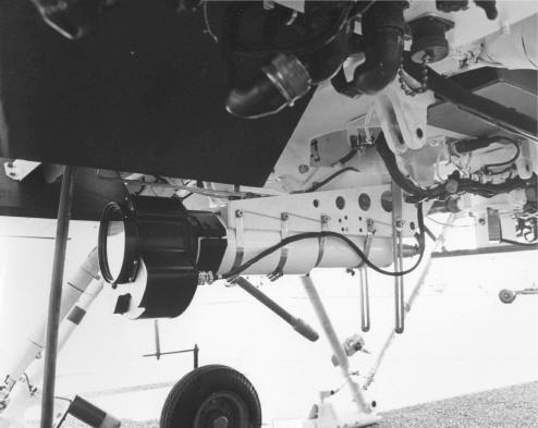
 Extended Range
Fuel System Extended Range
Fuel System
The
extended range fuel system modification to the QH-50 helicopter
provided approximately 80 gallons of additional fuel over and above the basic 52
gallons in the basic fuel tank, to be carried on a mission. Included in the
system were two 40-gallon auxiliary tanks and their associated plumbing and
check valves.
The auxiliary tanks were of
fiberglass construction and were mounted one on each side of the airframe. The
exteriors of the auxiliary tanks, in addition to the basic 52 gallon fuel tank,
were covered with a puncture sealing material.
Extended Altitude Range System
The conventional
altitude command system of the QH-50 helicopter was modified for Nite Panther to
provide two modes of control which were selectively available as follows:
1. Barometric
Resynchronization mode in which the baro is resynchronized to zero output at a
pressure corresponding to the actual altitude of the aircraft at the point of
resynchronization. Altitude command control for climb to and descent from
mission altitude was accomplished in increments of 600 feet maximum command
range.
2. Direct Collective mode in
which the normal barometric altitude control system was bypassed and the
collective pitch setting of the helicopter rotor blades was commanded directly
by the controller at the control station.
Either extended altitude range control mode could be remotely
selected from the control station.
Turn Coordination Disabling System
In order to prevent
loss of visual orientation of the TV camera during turns, it was considered
desirable to provide for the elimination of conventional banking of the QH-50
helicopter. To permit flat or uncoordinated turns, a means of disabling the turn
coordination system was provided in the Nite Panther vehicle. The turn
coordination system could be commanded in or out of the aircraft control system
remotely from either the shipboard or jeep control station.
Lateral Trim Capability
A lateral trim capability was
introduced into the command system primarily to compensate for drift of the
aircraft during the search and surveillance phases of a mission. This capability
existed only in the cruise mode of aircraft control and could be utilized at
both the shipboard and jeep control stations.
 Collective Limiting
Disabling Collective Limiting
Disabling
To improve drone stability in higher gross weight
configurations, the normal collective limiting system was disabled by removal of
RPM crossfeed from the control system.
Protective Armor
Protective armor was installed
on the Nite Panther vehicle to reduce its vulnerability to small arms ground
fire. Armor was placed forward, aft, and in lateral positions. Made of special
lightweight material, this armor was positioned to maximize protection of vital
portions of the QH-50 helicopter.
GYRODYNE Flight Testing of the NITE PANTHER Vehicles
Gyrodyne, at the completion of
the assembly of the Nite Panther vehicles, embarked on an accelerated ground and
flight test program to verify that the installation was satisfactory. These
tests were performed during the weeks of 25 March 1968, and 5 April 1968.
Among the three (3) vehicles DS-1700,
DS-1701, and DS-1702, a total of 10 hours ground time and 2. 7 hours flight time
were accumulated. Flight time was divided as follows:
Vehicle Serial No.
|
Duration in Hours
|
Number of Flights
|
DS-1700
|
0.7
|
5
|
DS-1701
|
0.7
|
3
|
DS-1702
|
1.3
|
5
|
Total
|
2.7 hours
|
13 Flights
|
These hours do not
include the hours accumulated during production acceptance tests of the
production configuration of QH-50 prior to incorporation of Nite Panther
hardware. The following was accomplished during these flight tests:
1. Day TV systems was thoroughly checked on
all three (3) vehicles.
2. Low light level TV system was checked on
DS-1701.
3. Laser installation was checked on DS-1700.
4. Telemetry systems incorporated on the vehicles were actually utilized
during the checkout of the drones. Further telemetry checks were made at San
Clemente Island during weeks of 8 April 1968, and 15 April 1968.
5. Nite Panther flight speed envelope (0 to 50 knots) was examined at
varying weights up to 2400 lbs.
6. Jeep station checks were made utilizing
the Nite Panther vehicles. Transfer of control to the Jeep was thoroughly
checked. Start capability was also checked.
Flights Conducted at San Clemente Prior to Deployment
Vehicle Serial No.
|
Date
|
Duration Hours
|
Number of Flights
|
DS-1700
|
9 April 68
|
1.6
|
3
|
|
10 April 68
|
0.7
|
1
|
|
11 April 68
|
0.3
|
1
|
|
Total prior to deployment
|
2.6
|
5
|
|
|
|
|
|
DS-1701
|
9 April 68
|
0.8
|
2
|
|
10 April 68
|
0.2
|
1
|
|
11 April 68
|
1.4
|
3
|
|
14 April 68
|
0.6
|
1
|
|
15 April 68
|
0.7
|
1
|
|
Total prior to deployment
|
3.7
|
8
|
|
|
|
|
|
DS-1702
|
6 April 68
|
0.6
|
1
|
|
|
7 April 68
|
0.1
|
1
|
|
16 April 68
|
0.2
|
1
|
|
17 April 68
|
2.3
|
2
|
|
|
Total prior to deployment
|
3.2
|
5
|
Performance Parameters
|
Configuration
|
Model QH-50D
|
Nite Panther *
|
Version
|
DASH
|
Day
|
Night
|
| Mission Gross Weight, Lb Mission Fuel Weight, lb
Mission Altitude, ft
Mission Airspeed, Knots
Mission Radius to Station, n.mi.
Station Airspeed, knots
Time on Station, hr. |
2327 348
Sea Level
80
47.2
55
0.6 |
2450 806
6000
60
41.8
0
1.9 |
2450 768
6000
60
41.8
0
1.7 |
* Please Note: The maximum design gross weight
for the Nite Panther configuration was originally set at 2400 lbs. With the
subsequent installation of the required Laser Rangefinder and other items, the
vehicle gross weight was increased substantially, well beyond the 2450 lbs. As a
result of this situation, a new permissible maximum gross weight of 2450 lb was
established, the fuel load was reduced, and the time on station was decreased
from the planned 2.0 hours.
Additional Performance Parameters
|
Configuration
|
Model QH-50D
|
Nite Panther
|
Version
|
DASH
|
Day
|
Night
|
|
Atmosphere |
Tropical |
Hot |
Tropical |
Hot |
|
|
|
|
|
|
Sea Level Temperature, Fahrenheit |
90 |
103 |
90 |
103 |
|
Maximum Airspeed at S.L., kn |
80 |
80 |
80 |
80 |
|
Maximum Airspeed at 5000 ft, kn |
80 |
80 |
73* |
69* |
|
Hovering Ceiling, ft |
7300 |
5800 |
4000 |
2500 |
|
Vertical Rate of Climb, MRP, S.L.,
fpm |
1700 |
1400 |
1000 |
600 |
* Please Note, these airspeeds were a function of the current rotor blade
and were the blade stall limitations.
|
Empty Weight Evolution of Nite Panther
|
QH-50D Production Configuration
|
Rotor Group (Lbs)
Body Group
Basic Structure (aft)
Alighting Gear Group
Flight Controls Group
System Controls
Propulsion Group
Instrument/Navigation Group
Electrical Group
Electronics Group
Armament provisions
Emergency Flotation Equipment
Fittings -Tie Down
Manufacturing Variations |
140.5
77.9
16.6
43.0
125.1
56.9
477.3
7.6
34.1
84.6
11.5
20.9
4.4
5.4 |
|
Weight EMPTY; Specification
|
1032.4 lbs
|
|
|
WEIGHT EMPTY
QH-50D MODIFIED CONFIGURATIONS
|
|
Weight Empty; Specification (Lbs) |
|
1032.4 |
|
Items Removed: |
|
91.3 |
|
Fuel System (Main) |
33.9 |
|
|
Ballast-Telemetry Simulation |
25.0 |
|
|
Armament provision |
11.5 |
|
|
Emergency Flotation |
20.9 |
|
|
Weight Empty; Revised |
|
941.1 |
|
Items Added: |
|
553.5 |
|
Fuel System (Main) |
69.0 |
|
|
Generator (Auxiliary) |
12.0 |
|
|
Telemetry |
27.8 |
|
|
Equipment and Tank Support |
61.5 |
|
|
Auxiliary Tank Installation |
126.0 |
|
|
TV Equipment (Fixed) |
152.2 |
|
|
Forward Armor |
41.0 |
|
|
Center Armor |
22.0 |
|
|
Laser Range Finder |
50.0 |
|
|
|
|
|
|
WEIGHT EMPTY; Modified (lbs) |
|
1494.6 |
|
|
|
|
WEIGHT EMPTY
QH-50D PANTHER CONFIGURATION-DAY
CAMERA
|
|
Weight Empty; Modified (Lbs) |
|
1494.6 |
|
Day Camera Configuration |
|
109.3 |
|
Cohu Camera |
10.0 |
|
|
Camera Support and Actuator |
19.3 |
|
|
Camera Harness |
3.0 |
|
|
Dynalens and Adapter |
6.5 |
|
|
Dynalens Harness |
1.5 |
|
|
KB-10A Camera |
7.5 |
|
|
Camera Mount |
0.5 |
|
|
Camera Harness |
1.0 |
|
|
Aft Armor |
60.0 |
|
|
Manufacturing Variation |
|
4.5 |
|
|
|
WEIGHT EMPTY; Panther (lbs)
|
|
1608.4
|
|
|
WEIGHT EMPTY
QH-50D PANTHER CONFIGURATION-NIGHT
CAMERA
|
|
Weight Empty; Modified (Lbs) |
|
1494.6 |
|
Night Camera Configuration |
|
147.3 |
|
I.T.T. Camera |
35.0 |
|
|
Camera Support |
25.8 |
|
|
Camera Harness |
3.0 |
|
|
Dynalens and Adapter |
8.0 |
|
|
Dynalens Harness |
1.5 |
|
|
Illuminator |
55.0 |
|
|
Illuminator Support |
18.0 |
|
|
Illuminator Harness |
1.0 |
|
|
|
|
|
Manufacturing Variation |
|
4.5 |
|
|
|
WEIGHT EMPTY; Panther (lbs)
|
|
1646.4
|
|
|
LOADING CONDITIONS - MISSION FUEL
QH-50D PANTHER
CONFIGURATION
|
|
|
DAY CAMERA |
NIGHT CAMERA |
|
|
|
|
|
OIL-Engine |
12.6 |
12.6 |
|
OIL-Transmission |
13.4 |
13.4 |
|
FUEL - Usable -Main |
328.0 |
313.0 |
|
FUEL - Unusable - Main |
4.0 |
4.0 |
|
FUEL - Usable - Auxiliary |
478.0 |
455.0 |
|
FUEL - Unusable - Auxiliary |
6.0 |
6.0 |
|
|
|
| USEFUL LOAD |
842.0 |
804.0 |
|
|
|
WEIGHT EMPTY; Panther
|
1608.4
|
1646.4
|
GROSS WEIGHT
|
2450.4
|
2450.4
|
NITE PANTHER - Epilogue
While the NITE PANTHER program was rushed
into production by ARPA as a tool to support the Marines in South Vietnam, it is
not known how successful the program was or what missions the Marines flew with
their aircraft. However, after the deployment to San Clemente island on April 7,
1968, the PANTHER team did not stay long. On 18 April 1968, the team deployed to
U.S. Navy destroyers for operations in the Pacific and eventually ended up on
the USS BLUE (DD-744). Of the three Nite Panther aircraft, each equipped to
fulfill a different mission, all were lost on the following dates:
1. On 24 April 1968, Operating from the USS BLUE (DD-744) off
Vietnam DS-1701 was lost.
2. On 27 April 1968, Operating from the USS BLUE (DD-744) off
Vietnam DS-1702 was lost.
3. On 28 April 1968, Operating from a Western Pacific Ship,
DS-1700 was lost.
Despite the losses, the ARPA technology that was developed from
NITE PANTHER was eventually used in other programs although the Marine Corps
never experimented with QH-50 VTOL-Unmanned Aerial Vehicles again.
DESCRIPTION OF DASH AIRBORNE AND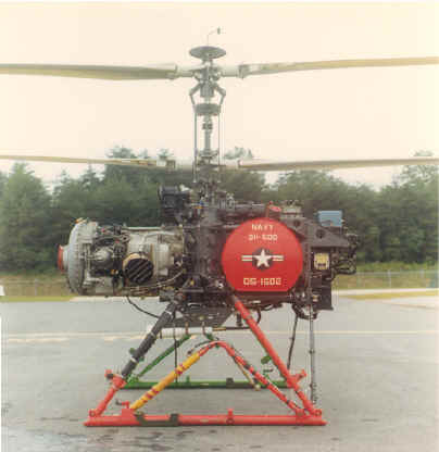 SHIPBOARD SYSTEM
The DASH (Drone Anti-Submarine Helicopter) System consisted of a Model
QH-50D vehicle (seen at right), which was a
remotely controlled coaxial helicopter originally designed for ASW mission for
delivery of two (2) MK-44 torpedoes while operating from a destroyer with
AN/SRW-4 DASH Command and Control capability.
Command and Control
Airborne
The remote control for DASH
consists of an airborne four-axis stabilization system and a receiver and
decoder units of the digital pulse control monitor (PCM) data link. The
four-axis stabilization system stabilizes the airborne vehicle in pitch, roll,
yaw and altitude. Rotor rpm was maintained constant by the engine governor, a
vertical gyro provides longitudinal (pitch) and lateral (roll) stability, and a
directional gyro provides yaw (heading) stability. The altitude axis
incorporates a barometric altitude sensing device. When a command was received
via the ground portion of the data link, it has the effect of giving the
particular axis commanded a new reference position.
Shipboard
The ship portion of the data
link was the Target Control System, AN/ SRW-4. When operated from a destroyer,
visual control of the drone was accomplished through the flight deck Transmitter
Control. Track to the target, release of weapon (s) and return to within visual
control was accomplished through the CIC (Combat Information Center) Transmitter
Control.
The CIC Transmitter Control was
designed to provide air speed altitude and heading selection; this mode of
operation was designated the "Cruise" mode, and was the only mode available in
CIC. The Deck Transmitter Control incorporates the "Cruise" mode for control
after take-off and prior to landing, plus a "Maneuver" mode for take-off and
landing control. The “Maneuver mode allows accurate positioning of the drone
through use of a maneuver stick. Heading and altitude were commanded through the
same knobs in both "Cruise" and "Maneuver" modes and, in addition, heading may
be changed at a constant rate by twisting the maneuver stick. In the "Cruise"
mode, turn coordination was provided within the stabilization system so that
lateral cyclic control was automatically applied when heading changes were
commanded.
General
Nine channels were incorporated in the data link system
for ON-OFF functions required for weapon arming and launching, engine stopping,
releasing the landing cable, and other functions where required. A feature of
the remote control system was the Memory function. It allowed the drone to
operate for an indefinite period using the last received command data. The loss
of a radio signal actuated the Carrier Loss function which placed the drone in a
hover condition at the last commanded altitude and heading.
Airframe
The basic Model QH-50 airframe consists of the following major
components which was of simple functional design requiring minimum maintenance
and allowing maximum access to the equipment:
Fuselage - The lower casting of the transmission forms
the main portion of the fuselage. Attached to the casting were the four
supporting struts for the skid-type landing gear, the two lower aft fuselage
tubes, and the bomb shackle and launcher mechanisms. The avionic equipment was
mounted on a vertical aluminum honeycomb sandwich structure which was supported
by four tubular members fitted into sockets on the transmission housings. The
honeycomb panel and tubular members form the aft fuselage frame into which the
fuel tank was nested for support.
 Transmission - The rotor transmission system consists of a two- stage gear
reduction, two coaxial rotor drive shafts, an integral lubricating system, a
generator drive and a rotary actuator drive. Power from the engine was
transmitted to the rotors through the two-stage gear reduction, the second stage
of which divides the torque to the two- counter-rotating co-axial rotor drive
shafts. The generator and rotary actuator were driven by means of accessory
drives in mesh with a single drive gear mounted on the lower rotor shaft.
Transmission - The rotor transmission system consists of a two- stage gear
reduction, two coaxial rotor drive shafts, an integral lubricating system, a
generator drive and a rotary actuator drive. Power from the engine was
transmitted to the rotors through the two-stage gear reduction, the second stage
of which divides the torque to the two- counter-rotating co-axial rotor drive
shafts. The generator and rotary actuator were driven by means of accessory
drives in mesh with a single drive gear mounted on the lower rotor shaft.
Rotor System - Two 20-foot diameter, 2-bladed,
semi-rigid counter- rotating coaxial rotors comprise the rotor system. The
blades were of fiberglass construction, incorporating linear taper in planform
and thickness and negative twist. Rotor controls were operated by the Automatic
Stabilization and Remote Control Equipment (ACSE). Control in pitch and roll was
achieved through conventional cyclic control of the swash plates. Collective
pitch control was obtained by conventional collective movement of the swash
plates. Control in yaw was achieved by movable tip brakes connected to both the
upper and lower rotor blade tips and provide positive directional control by
creating unequal torque distribution in the rotor system. A left-turning moment
results from the lower rotor tip brake deflection, and a right-turning moment
results from, the upper rotor tip brake deflection. In the neutral condition,
both sets of tip brakes were undeflected.
Fuel Tank - The fuel tank of the Model QH-50D has a
capacity of 52 gallons and was cylindrical in shape with its axis placed
laterally on the drone. The fuel tank was positioned aft of the transmission and
was secured by means of local cutouts and pads which permit it to be nested
within the aft fuselage tubular framework. The cylindrical tank has dome-shaped
ends and was reinforced by three circular baffles and one vertical baffle along
the tank axis.
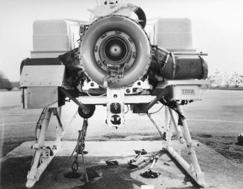
Power Plant - The power
plant for the QH-50D Drone was the Model T50-BO-12 Boeing Free Turbine, rated at
365 SHP at 6000 rpm, sea level standard conditions. The engine incorporates an
electric starter. The engine was attached rigidly to the forward face of the
transmission. The intake and gas producer section were forward and the power
section aft, abutting the transmission. Engine exhaust was directed sidewise,
outward and downward. The free turbine principle permits connecting the engine
drive directly to the transmission without a clutch installation.
|
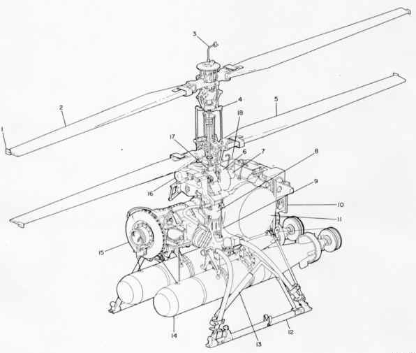 |
|
QH-50D Drone General Assembly Diagram |
| 1. Tip Brakes |
7. Airborne Generator |
13. Antenna |
| 2. Upper rotor assembly |
8. Transmission housing |
14. MK-44 Homing Torpedo |
| 3. Static pressure pick-up |
9. Fuselage frame and
transmission support housing |
15. Engine |
| 4. Rotating controls |
10. AFC set components |
16. Servo actuator |
| 5. Lower rotor assembly |
11. Fuel Tank |
17. Non-rotating controls |
|
6. Bell Housing |
12. Landing Gear |
|
Dimensions and General Data for the QH-50D
|
| Rotors |
|
| Type of Rotors |
Coaxial Semi-rigid |
| Number of Rotors |
Two |
| Blades per rotor |
Two |
| Rotor Diameter |
20 Feet |
| Disc Area |
314.2 Sq. ft. |
| Blade Cord |
|
| Root
(theoretical) |
13.000 inches |
| Tip (theoretical) |
6.500 inches |
|
|
| Dimensions |
|
| Max. Length (rotors) |
20 feet |
| Max. Height |
9 ft. 8.5 inches |
| Max. Width |
5 ft. 3 inches |
| Fuselage Length |
6 ft. 8.28 inches |
| Skid Length |
5 ft. 3.64 inches |
| Skid Tread |
5 ft. |

      
|